Model an ALU circuit in Rust
Do you love metal!? No, not that kind of metal. I’m talking about those periodic table elements that make up a computer. I thought so! Why else would you be here with a blog title like that? Well, I do, too. Lately, I’ve been reading the fantastic book, Dive Into Systems. It’s been the most enlightening yet succinct and specific experience I’ve had learning about the foundations of how computers work. It begins with the basics of C, which in my opinion is the best first language to learn because it easily allows you to create a mental model of how your code is manipulating the hardware without also having to think about other things like safety (oh, the overhead). But the sweet spot of the book is where it describes how the computation itself works, by manipulating electricity with logic gates and combining them together into abstractions all the way up to multithreaded operating systems. We are wizards wielding arcane magics. I highly recommend reading it if you’re not already familiar with this stuff1.
The path from logic gate to arithmetic logic unit (ALU) is fascinating, and it inspired me to implement it myself in software land. So I did. In Rust!
Logic Gates
Logic gates are simple circuits that are used as the foundation of building more complicated circuits. Those circuits are then combined to build even more complicated circuits which eventually make up an entire processor. Logic gates themselves are composed of transistors, which are itty bitty switches that control the flow of electricity. They are etched directly onto some semiconductor like silicon which makes up a microchip. Beneath the transistors? It’s turtles all the way down, don’t ask. Logic gates are about as fundamental is it gets for our task of circuit modeling, so we’ll stop there. We’ll use them to implement the basic boolean logic concepts of AND, OR, and NOT. Everything else can be built from these. First let’s start off with the truth tables:
x | y | AND | OR       x | NOT
----------------       -------
0   0    0    0        0    1
1   0    0    1        1    0
0   1    0    1
1   1    1    1
These ones and zeros represent the presence or absence of an electrical charge (which is controlled by transistors). The AND and OR gates take two one-bit inputs and produce a one-bit output resulting from the logic. I think a function could handle this nicely. First let’s enforce the truth tables as tests.
#[test]
fn and_gate_truth_table() {
    assert!(!and_gate(false, false));
    assert!(!and_gate(true, false));
    assert!(!and_gate(false, true));
    assert!(and_gate(true, true));
}

#[test]
fn or_gate_truth_table() {
    assert!(!or_gate(false, false));
    assert!(or_gate(true, false));
    assert!(or_gate(false, true));
    assert!(or_gate(true, true));
}
TDD is fun! Now the logic gates:
pub type Bit = bool;

pub fn and_gate(x: Bit, y: Bit) -> Bit {
    x & y
}

pub fn or_gate(x: Bit, y: Bit) -> Bit {
    x | y
}
Since we are only ever dealing with two values here, the bool type nicely represents
a bit. It’s basically just a u8 which is the smallest type in Rust and
allocates one byte of memory (way more than we need, but alas).
It can also be used with bitwise operators, which is what we’ve done. Now
for NOT.
#[test]
fn not_gate_truth_table() {
    assert!(not_gate(false));
    assert!(!not_gate(true));
}

pub fn not_gate(x: Bit) -> Bit {
    !x
}
Voila! It’s pretty neat how everything else you know about computers is built on top of these three gates. But now what? How do we go about arranging them like matches in order to build an ALU? Let’s jump up the abstraction tree to figure out what we actually want the ALU to do.
What are we doing here?
ALUs are the heart and soul of CPUs. It’s where all the magic happens. Everything else is just storage and control circuits to get what’s in storage into the ALU. And then what? Since we are building our own, what should we make it do? Since it stands for arithmetic and logic, it only makes sense to provide those two operations for our simple ALU: addition and equality. Also, for simplicity’s sake, let’s make it an 8-bit ALU. However, before we get to eight bits, we need to start with one.
Equality
To compare two bits with each other, we need a circuit that takes two one-bit inputs and returns one-bit that’s a 1 when they’re equal or a 0 when they’re not. We need a truth table!
#[test]
fn equals_truth_table() {
    assert!(equals(false, false)); // 0 and 0 -> 1
    assert!(!equals(true, false)); // 1 and 0 -> 0
    assert!(!equals(false, true)); // 0 and 1 -> 0
    assert!(equals(true, true));   // 1 and 1 -> 1
}
This is actually a great scenario for using test-driven development. Given a truth table, find some combination of logic gates to satisfy every truth. If you want to take a break and paper napkin this one, be my guest. I’ll wait.
This will be easier to grok with a circuit diagram:
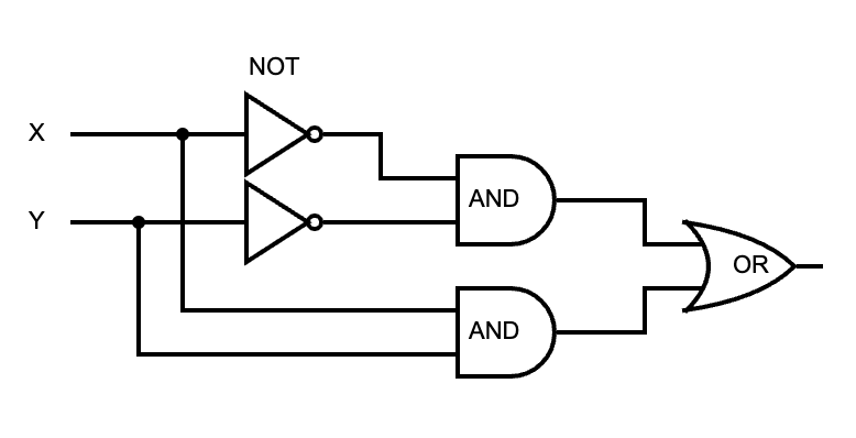
If either the AND of X and Y or the AND of the negation of X and Y is 1, then they are equal. This diagram can be mapped to a function that passes all the test cases.
fn equals(x: Bit, y: Bit) -> Bit {
    or_gate(
        and_gate(not_gate(x), not_gate(y)),
        and_gate(x, y)
    )
}
Great! We have a way of checking if two bits are equal. Except we are building an 8-bit ALU, so we need to be able to check if two 8-bit values are equal. Since we’re modeling individual bits with boolean values, we use a collection of them to represent a byte.
// Example byte: 10100011
let x = vec![true, false, true, false, false, false, true, true];
let y = vec![true, false, true, false, false, false, true, true];
m_bit_equals(x, y) // -> true
Here we have identical vectors of bits standing in for X and Y. To support equality
for these, we can compare the bit pairs individually with our equals function
and return 0 (false) at the first pair that is not equal, otherwise 1 (true) if
we’ve made it through the entire collection. This happens to support any number of bits, not just eight.
fn m_bit_equals(x: Vec<Bit>, y: Vec<Bit>) -> Bit {
    for (&x_bit, &y_bit) in x.iter().zip(y.iter()) {
        if !equals(x_bit, y_bit) {
            return false;
        }
    }
    true
}
ALU v1
Hooray! We have an 8-bit operation our machine can use. Let’s create the simplest ALU ever!
const BITS: usize = 8;
const EQ: Bit = false;

fn alu(_opcode: Bit, x: Vec<Bit>, y: Vec<Bit>) -> Vec<Bit> {
    let mut result = vec![false; BITS];
    result[BITS - 1] = m_bit_equals(x, y);
    result
}

alu(EQ, x, y) // -> vec![false, false, false, false, false, false, false, true]
The EQ opcode is zero since it’s the only one. We pass that and the two 8-bit
vectors defined earlier to the ALU function. It returns one 8-bit vector which is initialized
to 00000000. The M-bit equals circuit is executed and the least significant bit of the return
vector is set to the result. In this case, it’s true since our compared vectors are identical.
Therefore, the ALU returns 00000001.
The opcode is actually ignored right now, since there is only one operation.
Let’s change that and implement addition!
Addition
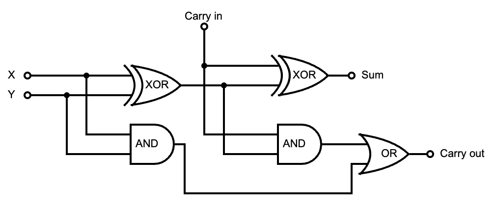
This circuit is a bit more complicated than equality, so this time around we’ll go straight to the diagram. The one-bit adder:
Remember, when dealing with addition, the sum may overflow the number base you are working with. It happens a lot in binary.
Base10                 Base2
11       carry over    11
 245                    111  7
+781                   +101  5
----                   ----
1026                   1100  12
We can consider each column in the Base2 addition to be a one-bit adder. It takes the two bits to add, and a carry-in bit from the previous adder. It returns the sum and a carry-out bit for the next adder. Here’s the truth table and function signature:
#[test]
fn one_bit_adder_truth_table() {
    assert_eq!(one_bit_adder(false, false, false), (false, false));
    assert_eq!(one_bit_adder(false, false, true), (true, false));
    assert_eq!(one_bit_adder(true, false, false), (true, false));
    assert_eq!(one_bit_adder(true, false, true), (false, true));
    assert_eq!(one_bit_adder(false, true, false), (true, false));
    assert_eq!(one_bit_adder(false, true, true), (false, true));
    assert_eq!(one_bit_adder(true, true, false), (false, true));
    assert_eq!(one_bit_adder(true, true, true), (true, true));
}

fn one_bit_adder(x: Bit, y: Bit, carry_in: Bit) -> (Bit, Bit) // (sum, carry_out)
Eagle eyed readers will notice that we are unable to implement the adder until we have one more tool to work with. The eXclusive OR gate! This gate returns 1 only when the two inputs are not equal and can be built from the three base gates:
#[test]
fn xor_gate_truth_table() {
    assert!(!xor_gate(false, false));
    assert!(xor_gate(true, false));
    assert!(xor_gate(false, true));
    assert!(!xor_gate(true, true));
}

fn xor_gate(x: Bit, y: Bit) -> Bit {
    or_gate(
        and_gate(x, not_gate(y)),
        and_gate(not_gate(x), y)
    )
}
And now the one-bit adder! Try to visualize how this codifies the circuit diagram.
fn one_bit_adder(x: Bit, y: Bit, carry_in: Bit) -> (Bit, Bit) {
    let half_sum = xor_gate(x, y);
    let carry_over1 = and_gate(x, y);

    let sum = xor_gate(half_sum, carry_in);
    let carry_over2 = and_gate(half_sum, carry_in);

    let carry_out = or_gate(carry_over1, carry_over2);
    (sum, carry_out)
}
But of course, we need to handle adding 8-bit numbers.
fn m_bit_adder(bits: usize, x: Vec<Bit>, y: Vec<Bit>) -> (Vec<Bit>, Bit) {
    let mut sum = vec![false; bits];
    let mut carry_out = false;
    let matched_bits: Vec<(&Bit, &Bit)> = x.iter().zip(y.iter()).collect();

    for idx in (0..bits).rev() {
        let (&a_bit, &b_bit) = matched_bits[idx];
        let result = one_bit_adder(a_bit, b_bit, carry_out);
        sum[idx] = result.0;
        carry_out = result.1;
    }

    (sum, carry_out)
}
Initialize the sum at 00000000, and carry over at 0. Pair all the bits together with zip.
Starting with the least significant bit (the highest index, thus rev), go over each pair
and put them through the one-bit adder. With each result, put that pair’s sum into
that index of the total sum and store the carry over. At the end, you have the
full sum and a remaining carry out. Now, let’s see how we can add this new operation to the ALU!
Another circuit, really?
The interesting thing about the operations in an ALU is that they are all executed at the same time. They’re just circuits, so the electrical charges sent into the ALU run through all the operational circuits contained therein at once. In our ALU, when we provide the operands, the equality circuit AND the addition circuit will both be lit up and produce a value. It’s the opcode that decides which one is actually chosen for output. How is this conditional logic implemented, you ask? Why, with a multiplexer!
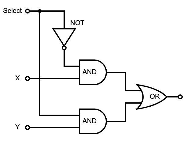
The Multiplexer!
This is a control circuit that selects one of multiple inputs. In the case of two one-bit values, a single select bit is passed in to determine which of the two inputs will be selected. This is a one-bit two-way multiplexer.
Que the truth table:
#[test]
fn two_way_mux_truth_table() {
    assert!(!two_way_mux(false, false, false));
    assert!(two_way_mux(false, true, false));
    assert!(!two_way_mux(true, false, false));
    assert!(two_way_mux(true, true, false));
    assert!(!two_way_mux(false, false, true));
    assert!(!two_way_mux(false, true, true));
    assert!(two_way_mux(true, false, true));
    assert!(two_way_mux(true, true, true));
}
As you can see, like the XOR gate, multiplexers can be built from just the three basic gates:
fn two_way_mux(x: Bit, y: Bit, select: Bit) -> Bit {
    or_gate(
        and_gate(x, not_gate(select)),
        and_gate(y, select),
    )
}
Using this one-bit mux, we can build an M-bit mux. We only have two operations to choose from, so it remains two-way.
fn m_bit_two_way_mux(a: Vec<Bit>, b: Vec<Bit>, select: Bit) -> Vec<Bit> {
    let matched_bits: Vec<(&Bit, &Bit)> = a.iter().zip(b.iter()).collect();
    let mut bits = Vec::with_capacity(matched_bits.capacity());
    for (&a_bit, &b_bit) in matched_bits {
        bits.push(two_way_mux(a_bit, b_bit, select));
    }
    bits
}
The bits are paired and each pair is put through the one-bit two-way mux with the same select bit. This effectively picks one of the two multi-bit input values. Now let’s put it all together! Execute all operations, then pick one. Powered by logic gates alone (mostly).
ALU v2
const BITS: usize = 8;
const EQ: Bit = false;
const ADD: Bit = true;

fn alu(opcode: Bit, x: Vec<Bit>, y: Vec<Bit>) -> Vec<Bit> {
    // ADD
    let (sum, _carry_out) = m_bit_adder(BITS, x.clone(), y.clone());

    // EQ
    let mut equal = vec![false; BITS];
    equal[BITS - 1] = m_bit_equals(x, y);

    // choose which circuit value to return
    m_bit_two_way_mux(sum, equal, opcode)
}

// 10100011
let x = vec![true, false, true, false, false, false, true, true];
let y = vec![true, false, true, false, false, false, true, true];

// 00000001 - vec![false, false, false, false, false, false, false, true]
let is_equal = alu(EQ, x, y);

// 01000110 - vec![false, true, false, false, false, true, true, false]
let sum = alu(ADD, x, y);
Final Summation
Pretty cool, huh? You just built the soul of a machine! If you wanted to add more operations to the ALU, you just add more lines to include the function calls for those operations. The only circuit that will need to change is the multiplexer. With N operation results to select, the number of select bits needs to increase by log2(N). For example, with four opcodes, you need two select bits; with eight opcodes, you need four select bits, etc.
If you’re feeling fiesty, you could expand on this and model the entire CPU. You’ll need RAM from which to load instructions and data, a register file for storage, instruction and program counter registers, and clock ticks that control the fetch, decode, execute, and write back cycles that use the ALU. That sounds nerdtastic! Dive Into Systems goes into detail about all of these concepts. I highly recommend it for further reading.
Notes
- 1: The Elements of Computing Systems is another similar book, but instead of just describing it, you actually build the stuff with hands on code.
- Circuit diagrams made at circuit-diagram.org